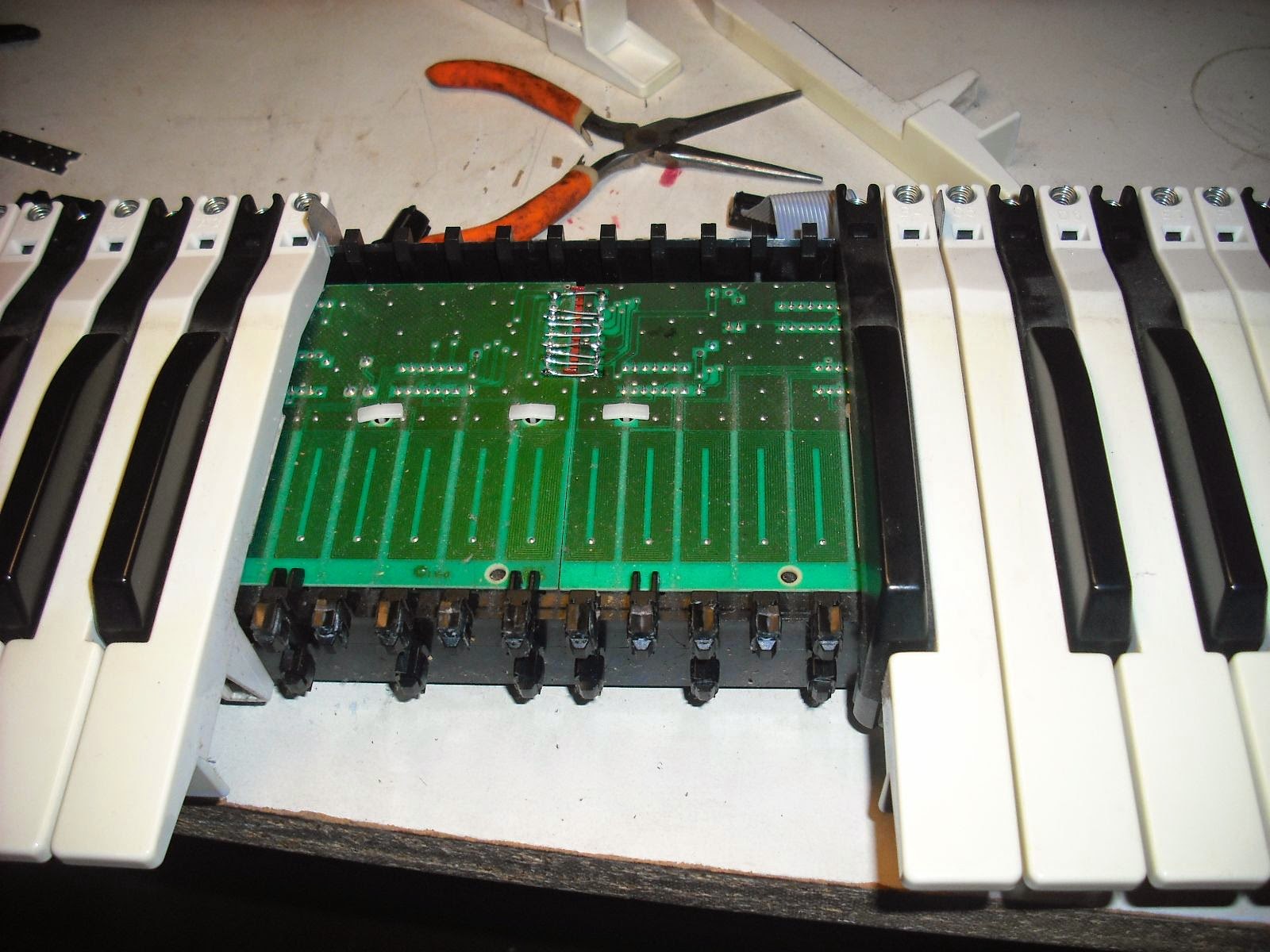
Since my previous post is also dealing with Ensonics; I would mention here that the VFX keyboard will sometimes say "calibration error" while trying to turn on. In addition to the obvious checking of the cabling to the keybed, it may also be necessary to remove the keys in the middle of the keybed, and bypass the socketed connection between the two circuit boards beneath with jumper wires as shown below.
THis keybend uses metal plates moving on top of sensors, creating an inductance, to measure velocity. It's a pretty neat scheme, unlike mostly all other touch sensitive keybeds which use rubber contacts. They are not as susceptible to dirt and dust.
On this particular keybed, some of those metal plates had to be glued back on to their respective keys; the customer had noticed that pressing hard on the keybed fixed the "calibration error" issue. However, over time and repeated pressings, he had dislodged the metal plates from the keys. Now that the jumper wires are soldered in place, he will no longer have to press on his keybed to get it to work!
Saturday, June 7, 2014
Ensonic EPS disk drive Replacement with HXC floppy emulator, no sound output on EPS
This post will deal with the replacement of 2 floppy disk drives with SD card "floppy emulators"; devices which allow the substitution of an SD card (or USB memory stick) for a floppy disk
.Among the many models out there, I used the floppy drive emulators from HXC. These come with excellent documentation and support, unlike some other emulators I have purchased form EBAY. I was also able to ascertain beforehand that they work on the EPS.
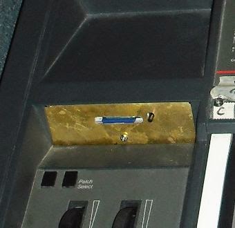
To save on cost, I used the slim model (less bells and whistles), and ordered simply the circuit board, not the enclosure. This made it necessary to fabricate a mounting scheme from wood and a brass plate... the result was actually appealing and kept the job under 200.00 per keyboard, parts and labor included. For a better aesthetic appearance, the supplier also sells a fabricated enclosure which probably would make the repair look less like a mod. But in this case, we wanted to keep costs down.
Incidentally, I have also purchased standard floppy drives and retrofitted them to the EPS and other Ensonic Models; I documented that on a previous blog post . These units used the older "shugart" interface, and require some pins redirected when attaching a PC style floppy drive.
But floppy drives and disks are getting rarer and harder to find. In general, I avoid installing them nowadays, in favor of the emulators.
If you look up HXC floppy emulators on the internet, you will find all the information you need in terms of ordering one and setting it up. The trick is knowing how to create disk images from your floppy disks, and how to format and put them onto the SD card.
You need to install a special driver on the PC you are using to read from the floppy disk, not the standard windows floppy disk driver. You then need to use software to convert the disk to the HFE format. You then need to copy this HFE image file to your SD card, and rename it DSKA0000.HFE . or DSKA0001.HFE,,,, you can put tons of images on the SD card but they all have to be named sequentially starting at 0 with the convention I just illustrated (DSKAxxxx.hfe), and they all have to have the .hfe extension. You also need to have a .cfg file on the SD card, the right one for the EPS, at all times. You can only put the images on the root of the SD card, along with the cfg file.
But once you jump through all these hoops, it truly works great in the end!
The only other issues with these EPS's was that the memory expander card needed to be removed, all the contacts cleaned, and then reseated. Issues with this card were causing there to be no sound output whatsoever on the unit.
Tuesday, May 20, 2014
Flat flexible cables: what to do when you encounter a broken one, or when you loose the little wedge that holds them in their socket:
Although often called a ribbon cable, this type of cable is actually an FFC, a flat flexible cable. Most of these cables are not unique, at least most of the ones I have encountered have an amount of contacts divisible by 10, and have either a .5 mm or 1 mm "pitch", which is the amount of space between the center of one contact to the center of the other.
They can be cut with a nice sharp pair of scissors, useful if you have encountered one where the end is a bit damaged, but may have enough conductive material left on it that you can fix it by just shortening it a bit. They can also be carefully cut vertically, if you have one that has too many wires ( is too wide).
On a few occasions I have received items for repair where the little wedge, that holds the ribbon cable into the socket, has been lost. That's a mistake I just don't make anymore... but many do.
I have had some success buying full replacement sockets from digikey and stealing the wedge (I think it's called a slide lock). The replacement sockets are not hard to find, as long as you have the correct number of contacts on the cable ends, and the right pitch, you may very likely find that exact socket for sale, and then use its wedge.
Of course, counting the number of contacts on the end of a tiny ribbon cable is kind of a pain.
When I have to do something like that, I take a nice digital picture of it, then blow it up on my computer screen, so I can slowly move my mouse over it and count out loud while I do it.
They can be cut with a nice sharp pair of scissors, useful if you have encountered one where the end is a bit damaged, but may have enough conductive material left on it that you can fix it by just shortening it a bit. They can also be carefully cut vertically, if you have one that has too many wires ( is too wide).
On a few occasions I have received items for repair where the little wedge, that holds the ribbon cable into the socket, has been lost. That's a mistake I just don't make anymore... but many do.
I have had some success buying full replacement sockets from digikey and stealing the wedge (I think it's called a slide lock). The replacement sockets are not hard to find, as long as you have the correct number of contacts on the cable ends, and the right pitch, you may very likely find that exact socket for sale, and then use its wedge.
Of course, counting the number of contacts on the end of a tiny ribbon cable is kind of a pain.
When I have to do something like that, I take a nice digital picture of it, then blow it up on my computer screen, so I can slowly move my mouse over it and count out loud while I do it.
Sunday, May 18, 2014
Chroma Polaris Membrane Repair
While repairing a Chroma Polaris, I was forced to disconnect the ribbon connectors (technically FFC connectors) that connect the membrane to the panel PCB's. To my horror, even though I was being painstakingly gentle and slow, one of them tore, almost immediately, as soon as I tried to move it
Additionally, the other 3 connectors -which didn't break as the first one did- still became cracked and intermittent when they were unbent from the position they had been resting in for 35 years.
In all cases, the cables broke where they had been bent... fairly close to the socket.
To repair the situation, I was able to cut the damaged portion off with scissors, and then grind away the insulating material (from the black side, not the silver side) with a wire brush attached to a dremel.
This may seem barbaric, but it actually worked flawlessly. ( I practice on the discarded portion of the ribbon cable first). You just need to buff it just enough so that you are able to ring through the traces on the ribon cable with your multimeter. If you buff it too much, you will grind through the conductive material, and render it useless. So you have to buff, and test, buff and test, until it rings through. It is naturally a good idea to practice first on the discarded portion of the ribbon cable.
On 3 of the connectors, I didn't have to shorten the cables too much, and they still stretched to their sockets
Either way, the repair has seemed to be permanent and hopefully the membrane will last another 30 years, especially if it is undisturbed. An additional step may be to recoat the exposed conductive part with conductive epoxy or paint; however it did not seem required in this situation.
One additional note: these flat ribbon cables are actually called FFC's, flat flexible cables. They are not called ribbon cables at all. Ribbon cables, technically, are made up of many insulated wires attached to each other. If these break, it is much easier to repair them. I am going to put up another post discussing FFC cables.
I also recapped the power supply and replaced a few faders.
AXIOM 49 with dead midi output
Nevertheless, this was the case here.
The unit came to me because the midi out was failing, it was completely dead. Of course I checked the jack and the connections around it, and all seemed fine. I reset the software.
Just for a lark, I removed the tiny small value capacitor that filtered the midi out line to ground, and found that the midi out came right back.
Although the capacitor did not read as shorted, it's capacitance must have drifted and increased significantly, enough to actually be filtering out the midi signal, rather than just noise.
It was a 220 PF cap, shown below, and the unit worked fine when it was removed, and continued to work fine when a new one was installed. The second picture shows the area where the cap was located... I believe labelled C4 on the silkscreen.
Sunday, April 6, 2014
Korg Triton LE Power Supply issues; heating up, distorted sound
This Triton came to me completely dead. The first thing I checked was the power supply, a 9v AC 3 amp wall supply with a 4 pin DIN connector... very much the same as some Alesis products... the DMPRO for example, which mentioned elsewhere in this blog.
I found a blown 2 amp inline fuse in the power supply, which can be disassembled (with the help of a drill). I am sure quite a few of these units have found their way to a trash can, with their only issue being this blown fuse. 2 amp fastblow and slow blow Pico fuses are available all over the internet.
After replacing the fuse, I turned the unit on, until to find that it was heating up, and only produced a horrid distorted tone.
I checked the voltage rails first, and noticed the 9 volt rail was substantially low. Through a process of elimination, and disconnecting one rail at a time, I came to find out that the 5 volt regulator had actually failed, and was sending excess voltage into the 5 volt rail, and consequently dragging down the other rails. It wasn't an extremely high voltage, at about 6 volts, and but it was enough to drag down the other rails.
This posed a substantial problem as this particular Korg uses a tiny surface mount switching regulator, and a tiny surface mount FET in conjunction with it. I found these parts in China, on ebay.
Once installed, the new regulator, fet, and a few caps (for good measure I replaced the filter capacitors around the regulator), the power rail came up and the unit turned on and worked. I also added a small 5.6 volt zener diode, which would short the rail to ground in case the voltage ever exceeds the specs again, in the hopes of protecting the chips.But this was too late...
Apparently, one of the PCM roms was damaged... probably by the previous over voltage, when the regulator first failed. There are four of these PCM roms on the Triton LE, and they provide the basis for all of the preset sounds and programs.
On this particular unit, after its resurrection, some of the sounds, predominantly the organs and some brass sounds, sounded great. But others were distorted... primarily all of the piano patches and string patches. These must be looking for those damaged PCM samples.
Sadly, Korg no longer supplies these PCM roms, and so we had to settle for a partial repair, until such a time as I can scavenge these chips.
On the bright side, the sampling feature was restored, and many of the cool organ patches.. and probably about 50% of all the other patches sound perfect. But there was nowhere I could obtain those PCM roms.
However, if someone reading this has an old triton LE mainboard for sale, from which we could scavenge these chips, please let me know!
I found a blown 2 amp inline fuse in the power supply, which can be disassembled (with the help of a drill). I am sure quite a few of these units have found their way to a trash can, with their only issue being this blown fuse. 2 amp fastblow and slow blow Pico fuses are available all over the internet.
After replacing the fuse, I turned the unit on, until to find that it was heating up, and only produced a horrid distorted tone.
I checked the voltage rails first, and noticed the 9 volt rail was substantially low. Through a process of elimination, and disconnecting one rail at a time, I came to find out that the 5 volt regulator had actually failed, and was sending excess voltage into the 5 volt rail, and consequently dragging down the other rails. It wasn't an extremely high voltage, at about 6 volts, and but it was enough to drag down the other rails.
This posed a substantial problem as this particular Korg uses a tiny surface mount switching regulator, and a tiny surface mount FET in conjunction with it. I found these parts in China, on ebay.
Once installed, the new regulator, fet, and a few caps (for good measure I replaced the filter capacitors around the regulator), the power rail came up and the unit turned on and worked. I also added a small 5.6 volt zener diode, which would short the rail to ground in case the voltage ever exceeds the specs again, in the hopes of protecting the chips.But this was too late...
Apparently, one of the PCM roms was damaged... probably by the previous over voltage, when the regulator first failed. There are four of these PCM roms on the Triton LE, and they provide the basis for all of the preset sounds and programs.
On this particular unit, after its resurrection, some of the sounds, predominantly the organs and some brass sounds, sounded great. But others were distorted... primarily all of the piano patches and string patches. These must be looking for those damaged PCM samples.
Sadly, Korg no longer supplies these PCM roms, and so we had to settle for a partial repair, until such a time as I can scavenge these chips.
On the bright side, the sampling feature was restored, and many of the cool organ patches.. and probably about 50% of all the other patches sound perfect. But there was nowhere I could obtain those PCM roms.
However, if someone reading this has an old triton LE mainboard for sale, from which we could scavenge these chips, please let me know!
Saturday, April 5, 2014
Korg CX3- old style- with Leaky Electrolytics
![]() |
| Dual CX-3! |
I am always skeptical when I receive these Cx3 organs for repair because of the known issues with the Seimens chips.. at the organ's heart are a couple of divide down oscillator chips that create the oscillations and gate them for each note. Their failure is a serious issue, because they are very hard to find and replace, and can only be replaced with other used chips that are probably very close to failure themselves. It seems someone was offering replacements, but apparently the supply dried up and I suppose they found it was no longer worth it to sell them.
But here was an instrument that didn't have that particular problem, rather it suffered from intermittent failures due to these badly leaking electrolytic capacitors seen below. The acid from inside of them ate through several traces on the boards, which had to be repaired.
The good news is that replacing them brought the keyboard back to life... the bad news is that there are about a thousand 10uF capacitors of this type sprinkled all throughout this keyboard. In this instance, due to financial and time constraints of the customer, we did replace only those that were seriously leaking... and left until later a full recapping, which is certainly necessary.
Currently the organ is working again, and sounding great, but most likely it will need some more caps replaced... unless the chips fail first!.
The failing capacitors were all 10 uF 16 volt capacitors. I doubt that it is coincidence... but it seems to me that the most frequent capacitors, in all gear, that I have to replace, are those rated 16 volts and less. I am not sure what is different between the processes used to make 16 volt caps and 35 and 50 volt capacitors, but I seem to rarely find failed 50 volt capacitors, unless they are too close to a heat source.
For this reason, I always use 50 volt capacitors, where possible, to replace them.
Subscribe to:
Posts (Atom)